Inverter circuit The schematic diagram of the full bridge inverter circuit with Single phase full bridge inverter (square wave output)
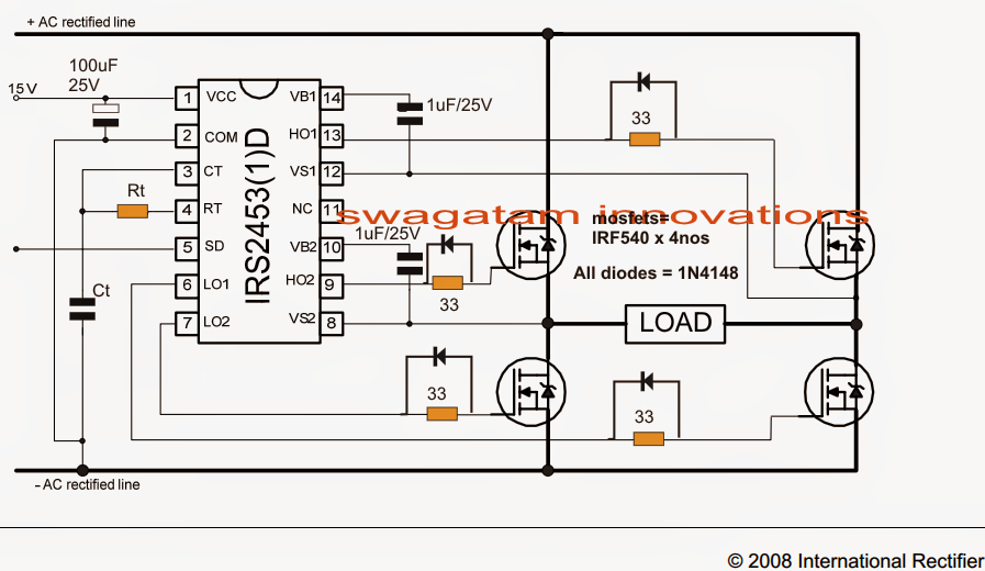
H-Bridge Inverter Circuit Using 4 N-channel Mosfets - Homemade Circuit
Full bridge inverter circuit diagram 3 phase inverter wiring diagram Single phase full bridge inverter explained
How do i calculated the outputted ac voltage of an h-bridge inverter
Inverter explained electricalbaba[diagram] h bridge inverter circuit diagrams Sg3525 full bridge inverter circuitInverter circuit bridge sg3525 using bootstrap mosfet diagram driver ic homemade circuits channel capacitor mosfets schematic try post investigate transformer.
Full bridge inverter circuit diagramInverter output resistive inductive Inverter explained electricalbabaSingle phase full bridge inverter.

Educatore genuino elettronico inverter h bridge mosfet circuit perizoma
Single phase full bridge inverter circuit [5]Inverter bridge circuit voltage ac calculated outputted do mosfet converting understand dc Sg3525 full bridge inverter circuitH bridge inverter circuit diagram.
Sg3525 inverter circuit bridge diagram using bootstrap mosfet driver homemade ic circuits channel capacitor mosfets pdf schematic try post investigateSingle phase half bridge and full bridge inverter circuit using matlab 10+ full bridge inverter circuit diagramSingle phase full bridge inverter explained.

[diagram] h bridge inverter circuit diagram
Full bridge inverterSingle phase full bridge inverter Inverter voltage scr wiring thyristor hvdc tyristor inverting simulation explainedH-bridge inverter circuit using 4 n-channel mosfets.
Inverter bridge circuit homemade using circuits wave sine mosfets modified channel kvaSimplest full bridge inverter circuit Circuit diagram inverter bridge supply power phase single seekicInverter bridge circuit diagram.
![[DIAGRAM] H Bridge Inverter Circuit Diagram - MYDIAGRAM.ONLINE](https://i2.wp.com/www.seekic.com/uploadfile/ic-circuit/2011327224443172.jpg)
Inverter circuit operation waveforms controlled
Inverter mosfet 12v outputs connections needsSingle phase full bridge inverter Single phase full bridge inverter[diagram] h bridge inverter circuit diagrams.
Schematic diagram of single phase full-bridge inverter circuitBridge inverter circuit diagram elprocus source phase Inverter circuit bridge phase 5kva ic using ac single core diagram mosfet transformerless ferrite pwm simplest driver gate 2kva circuitsEasy 150 w full-bridge inverter circuit [tested].

Inverter phase diagram principle
[diagram] h bridge inverter circuit diagramSingle phase half bridge inverter explained H-bridge inverter circuit using ic irs2453(1)d3 phase power circuit diagram.
Inverter single bridge phase source scr supply dc .

Single Phase Full Bridge Inverter | Electrical Revolution

Single Phase Full Bridge Inverter - Circuit Diagram, Working

10+ Full Bridge Inverter Circuit Diagram | Robhosking Diagram

H Bridge Inverter Circuit Diagram

Single Phase Full Bridge Inverter - Circuit Diagram, Working

Full Bridge Inverter Circuit Diagram
![[DIAGRAM] H Bridge Inverter Circuit Diagrams - MYDIAGRAM.ONLINE](https://i2.wp.com/www.homemade-circuits.com/wp-content/uploads/2019/05/Simple-transistor-full-bridge-inverter.jpg)
[DIAGRAM] H Bridge Inverter Circuit Diagrams - MYDIAGRAM.ONLINE